
In this chapter, we will discuss how to add page numbers in Word 2010. Microsoft Word automatically assigns page numbers on the pages of your document. Typically, page numbers are printed either in header or footer but you have the option that can display the page number in the left or right margins at the top or the bottom of a page.
Add Page Numbers
Following are the simple steps to add page numbers in a Word document.
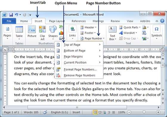
Step 1 − Click the Insert tab, and click the Page Number button available in the header and footer section. This will display a list of options to display the page number at the top, bottom, current position etc.
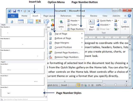
Step 2 − When you move your mouse pointer over the available options, it displays further styles of page numbers to be displayed. For example, when I take the mouse pointer at the Bottom of Page option it displays the following list of styles.
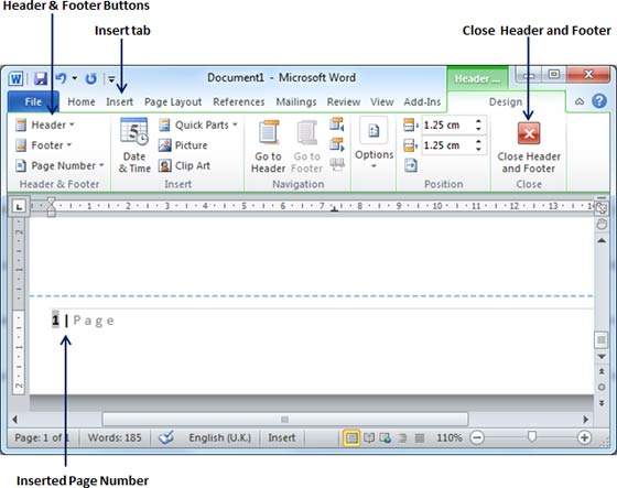
Step 3 − Finally, select any one of the page number styles. I selected the Accent Bar 1 style by clicking over it. You will be directed to the Page Footer modification mode. Click the Close Header and Footer button to come out of the Footer Edit mode.
You can format your page numbers using the Format Page Numbers option available under the listed options.
Remove Page Numbers
The following steps will help you remove page numbering from a Word document.
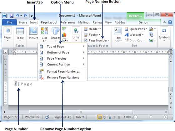
Step 1 − Click the Insert tab, and click the Page Number button available in the header and footer section. This will display a list of options to display page number at the top, bottom, current position, etc. At the bottom, you will have the Remove Page Numbers option. Just click this option and it will delete all the page numbers set in your document.
Comments
Post a Comment