
Decoder is a combinational circuit that has ‘n’ input lines and maximum of 2noutput lines. One of these outputs will be active High based on the combination of inputs present, when the decoder is enabled. That means decoder detects a particular code. The outputs of the decoder are nothing but the min terms of ‘n’ input variables (lines), when it is enabled.
2 to 4 Decoder
Let 2 to 4 Decoder has two inputs A1 & A0 and four outputs Y3, Y2, Y1 & Y0. The block diagram of 2 to 4 decoder is shown in the following figure.
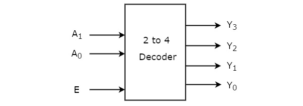
One of these four outputs will be ‘1’ for each combination of inputs when enable, E is ‘1’. The Truth table of 2 to 4 decoder is shown below.
| Enable | Inputs | Outputs | ||||
|---|---|---|---|---|---|---|
| E | A1 | A0 | Y3 | Y2 | Y1 | Y0 |
| 0 | x | x | 0 | 0 | 0 | 0 |
| 1 | 0 | 0 | 0 | 0 | 0 | 1 |
| 1 | 0 | 1 | 0 | 0 | 1 | 0 |
| 1 | 1 | 0 | 0 | 1 | 0 | 0 |
| 1 | 1 | 1 | 1 | 0 | 0 | 0 |
From Truth table, we can write the Boolean functions for each output as
Each output is having one product term. So, there are four product terms in total. We can implement these four product terms by using four AND gates having three inputs each & two inverters. The circuit diagram of 2 to 4 decoder is shown in the following figure.
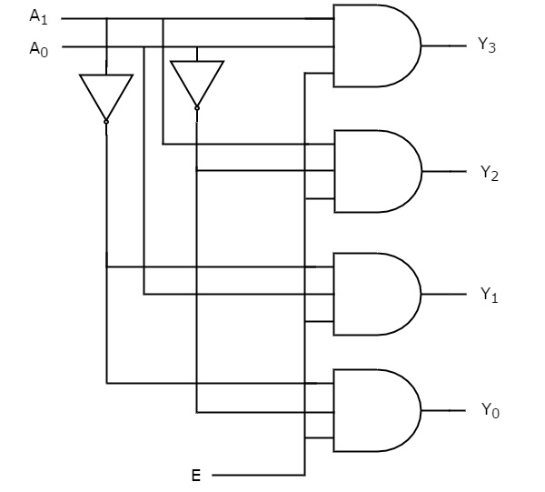
Therefore, the outputs of 2 to 4 decoder are nothing but the min terms of two input variables A1 & A0, when enable, E is equal to one. If enable, E is zero, then all the outputs of decoder will be equal to zero.
Similarly, 3 to 8 decoder produces eight min terms of three input variables A2, A1 & A0 and 4 to 16 decoder produces sixteen min terms of four input variables A3, A2, A1 & A0.
Implementation of Higher-order Decoders
Now, let us implement the following two higher-order decoders using lower-order decoders.
- 3 to 8 decoder
- 4 to 16 decoder
3 to 8 Decoder
In this section, let us implement 3 to 8 decoder using 2 to 4 decoders. We know that 2 to 4 Decoder has two inputs, A1 & A0 and four outputs, Y3 to Y0. Whereas, 3 to 8 Decoder has three inputs A2, A1 & A0 and eight outputs, Y7 to Y0.
We can find the number of lower order decoders required for implementing higher order decoder using the following formula.
Where,
is the number of outputs of lower order decoder.
is the number of outputs of higher order decoder.
Here, = 4 and = 8. Substitute, these two values in the above formula.
Therefore, we require two 2 to 4 decoders for implementing one 3 to 8 decoder. The block diagram of 3 to 8 decoder using 2 to 4 decoders is shown in the following figure.
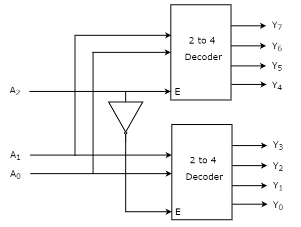
The parallel inputs A1 & A0 are applied to each 2 to 4 decoder. The complement of input A2 is connected to Enable, E of lower 2 to 4 decoder in order to get the outputs, Y3 to Y0. These are the lower four min terms. The input, A2 is directly connected to Enable, E of upper 2 to 4 decoder in order to get the outputs, Y7to Y4. These are the higher four min terms.
4 to 16 Decoder
In this section, let us implement 4 to 16 decoder using 3 to 8 decoders. We know that 3 to 8 Decoder has three inputs A2, A1 & A0 and eight outputs, Y7 to Y0. Whereas, 4 to 16 Decoder has four inputs A3, A2, A1 & A0 and sixteen outputs, Y15 to Y0
We know the following formula for finding the number of lower order decoders required.
Substitute, = 8 and = 16 in the above formula.
Therefore, we require two 3 to 8 decoders for implementing one 4 to 16 decoder. The block diagram of 4 to 16 decoder using 3 to 8 decoders is shown in the following figure.
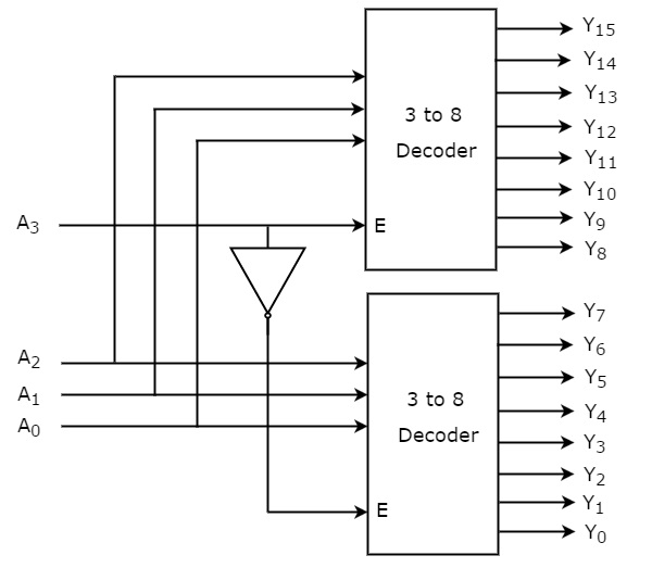
The parallel inputs A2, A1 & A0 are applied to each 3 to 8 decoder. The complement of input, A3 is connected to Enable, E of lower 3 to 8 decoder in order to get the outputs, Y7 to Y0. These are the lower eight min terms. The input, A3 is directly connected to Enable, E of upper 3 to 8 decoder in order to get the outputs, Y15 to Y8. These are the higher eight min terms.
Comments
Post a Comment